5G PCI Is Not Just a Number: What RF Engineers Must Know
Learn how 5G PCI planning affects cell detection, handovers and channel estimation, from collision and confusion to mod 3, mod 4 and mod 30 rules.
5G PCI Is Not Just a Number: What RF Engineers Must Know
Early in my career, PCI planning was a task for the newest engineer on the team: assign values, avoid repeats between neighbors, done. I still find networks where that mindset explains problems nobody can trace.
In 5G NR there are 1008 PCIs, built from two components: NID1, from 0 to 335, and NID2, from 0 to 2. That structure drives synchronization signals and reference signal patterns, so the value you assign has physical consequences.
Some things worth keeping in mind:
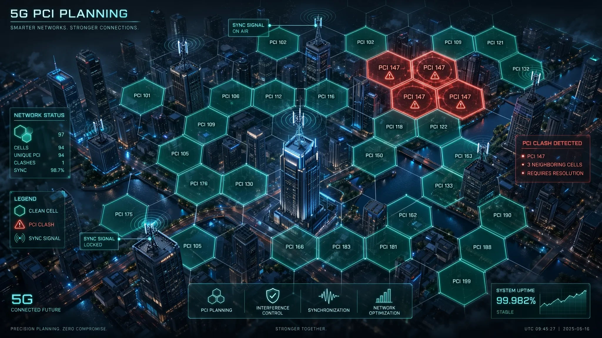
🔹 PCI collision happens when two overlapping cells share the same value, and the UE simply cannot tell them apart. 🔹 PCI confusion appears when a serving cell has two neighbors with the same PCI, which sends handovers to the wrong target. 🔹 Mod 3 matters because NID2 defines the PSS, and neighbors with the same remainder make cell detection harder in overlap zones. 🔹 Mod 4 drives the PBCH DMRS position and mod 30 affects uplink DMRS sequences by default, so clashes there quietly degrade channel estimation.
Having 1008 values feels like plenty until overshooting cells, dense small cell layers and multiple carriers shrink the real reuse distance.
Changing a PCI usually means taking the cell down briefly, so mistakes are not cheap to fix. That is why automated PCI planning in SON, combined with ANR to detect confusion early, has become standard practice in mature networks.
A clean PCI plan rarely gets noticed. A bad one shows up everywhere, just under a different name.
#5G #PCI #5GNR #RFOptimization #RANDesign #SON #RANEngineering